1
2
3
4
5
6
7
8
9
10
11
12
13
14
15
16
17
18
19
20
21
22
23
24
25
26
27
28
29
30
31
32
33
34
35
36
37
38
39
40
41
42
43
44
45
46
47
48
49
50
51
52
53
54
55
56
57
58
59
60
61
62
63
64
65
66
67
68
69
70
71
72
73
74
75
76
77
78
79
80
81
82
83
84
85
86
87
88
89
90
91
92
93
94
95
96
97
98
99
100
101
102
103
104
105
106
107
108
109
110
111
112
113
114
115
116
117
118
119
120
121
122
123
124
125
126
127
128
129
130
131
132
133
134
135
136
137
138
139
140
141
142
143
144
145
146
147
148
149
150
151
152
153
154
155
156
157
158
159
160
161
162
163
164
165
166
167
168
169
170
171
172
173
174
175
176
177
178
179
180
181
182
183
184
185
186
187
188
189
190
191
192
193
194
195
196
197
198
199
200
201
202
203
204
205
206
207
208
209
210
211
212
213
214
215
216
217
218
219
220
221
222
223
224
225
226
227
228
229
230
231
232
233
234
235
236
237
238
239
240
241
242
243
244
245
246
247
248
249
250
251
252
253
254
255
256
257
258
259
260
261
262
263
264
265
266
267
268
269
270
271
272
273
274
275
276
277
278
279
280
281
282
283
284
285
286
287
288
289
290
291
292
293
294
295
296
297
298
299
300
301
302
303
304
305
306
307
308
309
310
311
312
313
314
315
316
317
318
319
320
321
322
323
324
325
326
327
328
329
330
331
332
333
334
335
336
337
338
339
340
341
342
343
344
345
346
347
348
349
350
351
352
353
354
355
356
357
358
359
360
361
362
363
364
365
366
367
368
369
370
371
372
373
374
375
376
377
378
379
380
381
382
383
384
385
386
387
388
389
390
391
392
393
394
395
396
397
398
399
400
401
402
403
404
405
406
407
408
409
410
411
412
413
414
415
416
417
418
419
420
421
422
423
424
425
426
427
428
429
430
431
432
433
434
435
436
437
438
439
440
441
442
443
444
445
446
447
448
449
450
451
452
453
454
455
456
457
458
459
460
461
462
463
464
465
466
467
468
469
470
471
472
473
474
475
476
477
478
479
480
481
482
483
484
485
486
487
488
489
490
491
492
493
494
495
496
497
498
499
500
501
502
503
504
505
506
507
508
509
510
511
512
513
514
515
516
517
518
519
520
521
522
523
524
525
526
527
528
529
530
531
532
533
534
535
536
537
538
539
540
541
542
543
544
545
546
547
548
549
550
551
552
553
554
555
556
557
558
559
560
561
562
563
564
565
566
567
568
569
570
571
572
573
574
575
576
577
578
579
580
581
582
583
584
585
586
587
588
589
590
591
592
593
594
595
596
597
598
599
600
601
602
603
604
605
606
607
608
609
610
611
612
613
614
615
616
617
618
619
620
621
622
623
624
625
626
627
628
629
630
631
632
633
634
635
636
637
638
639
640
641
642
643
644
645
646
647
648
649
650
651
652
653
654
655
656
657
658
659
660
661
662
663
664
665
666
667
668
669
670
671
672
673
674
675
676
677
678
679
680
681
682
683
684
685
686
687
688
689
690
|
%global _empty_manifest_terminate_build 0
Name: python-anasymod
Version: 0.4.0
Release: 1
Summary: Tool for running mixed-signal emulations on FPGAs
License: BSD 3-Clause "New" or "Revised" License
URL: https://github.com/sgherbst/anasymod
Source0: https://mirrors.nju.edu.cn/pypi/web/packages/d1/17/b680f6ec8e307dc8bc94e0bef90ac5f415902dcc362eab6af2346872f6ec/anasymod-0.4.0.tar.gz
BuildArch: noarch
%description
# anasymod
[](https://github.com/sgherbst/anasymod/actions)
[](https://buildkite.com/stanford-aha/anasymod)
[](https://codecov.io/gh/sgherbst/anasymod)
[](https://opensource.org/licenses/BSD-3-Clause)
[](https://gitter.im/sgherbst/anasymod?utm_source=badge&utm_medium=badge&utm_campaign=pr-badge&utm_content=badge)
**anasymod** is a tool for running FPGA emulations of mixed-signal systems. It supports digital blocks described with Verilog or VHDL and synthesizable analog models created using [msdsl](https://github.com/sgherbst/msdsl) and [svreal](https://github.com/sgherbst/svreal).
# Installation
## From PyPI
```shell
> pip install anasymod
```
If you get a permissions error when running one of the **pip** commands, you can try adding the **--user** flag to the **pip** command. This will cause **pip** to install packages in your user directory rather than to a system-wide location.
## From GitHub
If you are a developer of **anasymod**, it is more convenient to clone and install the GitHub repository:
```shell
> git clone https://github.com/sgherbst/anasymod.git
> cd anasymod
> pip install -e .
```
## Testing the Installation
Check to see if the **anasymod** command-line script is accessible by running:
```shell
> anasymod -h
```
If the **anasymod** script isn't found, then you'll have to add the directory containing it to the path. On Windows, a typical location is **C:\\Python3\*\\Scripts**, while on Linux or macOS you might want to check **~/.local/bin** (particularly if you used the **--user** flag).
# Prerequites to run the examples
The examples included with **anasymod** use [Icarus Verilog](http://iverilog.icarus.com) for running simulations, [Xilinx Vivado](https://www.xilinx.com/products/design-tools/vivado.html) for running synthesis and place-and-route, and [GTKWave](http://gtkwave.sourceforge.net) for viewing the simulation and emulation results. The instructions for setting up these tools are included below for various platforms.
## Windows
Install Xilinx Vivado by going to the [downloads page](https://www.xilinx.com/support/download.html). Scroll to the latest version of the "Full Product Installation", and download the Windows self-extracting web installer. Launch the installer and follow the instructions. You'll need a Xilinx account (free), and will have to select a license, although the free WebPACK license option is fine you're just planning to work with small FPGAs like the one on the Pynq-Z1 board.
GTKwave and Icarus Verilog can be installed at the same time using the latest Icarus binary [here](http://bleyer.org/icarus/).
## Linux
Install Xilinx Vivado by going to the [downloads page](https://www.xilinx.com/support/download.html). Scroll to the latest version of the "Full Product Installation", and download the Linux self-extracting web installer. Then, in a terminal:
```shell
> sudo ./Xilinx_Vivado_SDK_Web_*.bin
```
A GUI will pop up and guide you through the rest of the installation. Note that you'll need a Xilinx account (free), and that you can select the free WebPACK license option if you're planning to work with relatively small FPGAs like the one on the Pynq-Z1 board.
Next, the Xilinx cable drivers must be installed ([AR #66440](https://www.xilinx.com/support/answers/66440.html)):
```shell
> cd <YOUR_XILINX_INSTALL>/data/xicom/cable_drivers/lin(32|64)/install_script/install_drivers
> sudo ./install_drivers
```
Finally, some permissions cleanup is required ([AR #62240](https://www.xilinx.com/support/answers/62240.html))
```shell
> cd ~/.Xilinx/Vivado
> sudo chown -R $USER *
> sudo chmod -R 777 *
> sudo chgrp -R $USER *
```
Installing GTKWave and Icarus Verilog is much simpler; just run the following in a terminal:
```shell
> sudo apt-get install gtkwave iverilog
```
## macOS
The simulation part of this example should work if you install Icarus Verilog and GTKWave:
```shell
> brew install icarus-verilog
> brew install --cask gtkwave
```
Unfortunately Xilinx Vivado does not run natively on macOS. However, running Vivado on a Windows or Linux virtual machine on macOS does seem to work.
## Running a Simulation
From within the folder **unittests**, run
```shell
> anasymod -i buck --models --sim --view
```
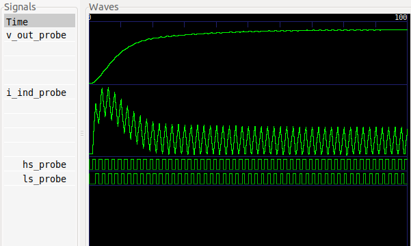
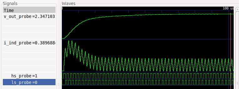
This will generate a synthesizable model for a buck converter, run a simulation, and display the results.
### Command-line options
Here's a breakdown of what the options mean:
* The **-i buck** option indicates that the folder ``buck`` contains the emulation files
* **--models** means that **anasymod** should look for a file called **gen.py** and run it. In this case the **gen.py** script uses [msdsl](https://git.io/msdsl) to generate a synthesizable model for the buck converter.
* **--sim** means that a simulation should be run on the computer, rather than building the emulator bitstream. This is helpful for debugging. You can also pass the option **--simulator_name NAME** to specify which simulator should be used. Currently supported simulators are **icarus**, **vivado**, and **xrun** (Cadence Xcelium),
* **--view** means that the resuls should be displayed after running the simulation. The viewer can be specified with the **--viewer_name NAME** option. Only **gtkwave** is supported at the moment. When a file called **view.gtkw** is in the folder with emulator sources, **anasymod** will load it to configure the GTKWave display. You can generate your own **view.gtkw** file using ``File`` → ``Write Save File`` in GTKWave.
### Source files
Looking into the ``buck`` folder, you'll notice there are a bunch of files. Some have special meanings for the **anasymod** tool (i.e., if you have a file with one of these names, it **anasymod** will treat it in a certain way)
* ``gen.py``: Generates synthesizable emulation models. **anasymod** expects to run this as a command-line script that has arguments ``-o`` (output directory) and ``-dt`` (fixed timestep). **anasymod** fills those arguments based on user settings when it runs **gen.py**.
* ``prj.yaml``: YAML file containing settings for the project, like the FPGA board to use, build options, emulator control infrastructure to use, etc. In this case, one of the key options is **dt**, which indicates that each emulator cycle corresponds to a fixed timestep of 50 ns.
* ``simctrl.yaml``: YAML file containing signals to probe. The signals indicated will be probed for both simulation and emulation (in the latter case, using a Xilinx Integrated Logic Analyzer instance). This file can also specify signals to be written and read in interactive tests.
* ``tb.sv``: Top-level file for simulation and synthesis, representing a synthesizable testbench.
**anasymod** has other special files (e.g., ``clks.yaml` for controlling clock generation), but they are not used in this example.
## Running an Emulation
At this point, we have run a simulation of the emulator design, but haven't built a bitstream of programmed the FPGA. This section shows how to run those tasks.
For this test to work as-is, you'll need a [Pynq-Z1](https://store.digilentinc.com/pynq-z1-python-productivity-for-zynq-7000-arm-fpga-soc/) board. However, if you uncomment the ``board_name`` option in ``prj.yaml``, you can specify a different board; currently supported options are ``PYNQ_Z1``, ``ARTY_A7``, ``VC707``, ``ZC702``, ``ZC706``, ``ZCU102``, and ``ZCU106``. We are always interested to add support for new boards, so please let us know if your board isn't listed here (feel free to file a GitHub Issue).
Go to the folder **unittests** and run the following command. It will take about 11 minutes to build the bitstream.
```shell
> anasymod -i buck --models --build
```
If you are using the Pynq-Z1 board, then please make sure it is set up correctly:
1. Jumper JP4 should be set for "JTAG"
2. Jumper "JP5" should be set for "USB"
Then, plug the Pynq board into your computer using a micro USB cable. Move the Pynq board power switch to "ON".
Run the emulation and view the results with the following command:
```shell
> anasymod -i buck --emulate --view
```
For now, there is a separate ``*.gtkw`` file used when viewing emulation results, which is ``view_fpga.gtkw``.
## Timestep Management
The example considered so far used a fixed timestep, but for optimal emulator performance, some systems benefit from an event-driven approach, where various blocks make timestep requests, resulting in a variable timestep emulator.
With **anasymod**, an emulation model can make a timestep request (``dt_req``), which is passed to an auto-generated time manager. The time manager takes the minimum of all timestep requests, and passes the result (``emu_dt``) back to models that need that information.
This system is configured through a file called ``clks.yaml``. For an example, see ``unittests/multi_clock``, which represents a system where two independent oscillators are running at different frequencies, and each is making its own timestep requests.
If you look in the top-level file (``tb.sv``), you'll see that there are two oscillator instances, ``osc_0`` and ``osc_1``. These are referenced in ``clks.yaml``, which says that **anasymod** should wire up the timestep request from each (``dt_req``) as well as the emulator timestep (``emu_dt``). It also connects up the emulator clock (``emu_clk``) and reset signals (``emu_rst``).
This brings us to a point about postprocessing: when you run a simulation or emulation, the raw data produced is dumped to a folder called ``raw_results``, and includes a timestamp at each emulation cycle. To make the results easier to visualize, **anasymod** post-processes the raw data, applying timestamps to all signals. The post-processed result is placed in a folder called ``vcd``; that waveform is what is displayed when you invoke the **--view** option. However, for debugging timestep issues, it can be useful to examine the ``raw_results`` folder, too.
## Clock Generation
The same ``clks.yaml`` file also handles the generation of new clock signals. **anasymod** automatically generates an emulator clock signal, but typically there are one or more "real" clocks in the design that need to be generated as well.
This takes some care to avoid timing issues, and the strategy taken by **anasymod** is to make sure the rising and falling edges of all generated clocks are aligned to a rising edge of the emulator clock. For a block that wants to generate a new clock signal, it produces a clock request (``gated_clk_req``) in the preceding emulator cycle, like a clock enable signal, and **anasymod** passes the generated clock signal (``gated_clk``) back to the block. The generated clock is properly aligned and routed through FPGA clock infrastructure to ensure good performance.
You can see an example of this configuration by examing the ``clk_0`` and ``clk_1`` entries in ``clks.yaml`` of the ``multi_clock`` example: the oscillator models each produce a clock request, and each clock request is used to generate one clock signal.
## Firmware
Rather than writing tests entirely in RTL, or controlling tests entirely from a host computer, it is often a good compromise to use firmware running on the FPGA to receive commands from the host computer and implement them at a lower level when interacting with the code in ``tb.sv``.
For FPGAs that contain a Processing System (PS), **anasymod** automates much of this process by automatically instantiating the PS and generating firmware to interact with it. An example can be seen in ``unittests/custom_firmware``, where user code, written in ``main.c`` invokes ``GET`` and ``SET`` commands from the auto-generated``gpio_funcs.h`` header.
The signals to be set up for reading and writing are specified in ``simctrl.yaml``, just as they would be for VIO-based control. However, the ``fpga_sim_ctrl`` setting in ``prj.yaml`` indicates that VIO control should not be used, and that the FPGA should instead using PS firmware to interact with the DUT.
By default, **anasymod** will generate a ``main.c`` file, but if you want to use your own, as in this example, set ``custom_zynq_firmware`` to ``True`` in ``prj.yaml``, and then specify the location of the ``main.c`` file in ``source.yaml`` (under ``firmware_files``).
## Interactive Tests
It's often important to be able to interact with the emulator from Python while it is running, is order to steer the high-level direction of the tests. This is supported through the ``Analysis`` object provided by the **anasymod** Python package, which provides a programmatic way to access all of the features of the command-line **anasymod** tool.
As an example, consider the example in ``unittests/rc``, which is an RC filter whose input and output are accessible for interactive testing (as specifed in its ``simctrl.yaml`` file).
With the **anasymod** programmatic interface, it's possible to build a bitstream, program the FPGA, and interact with the emulator with a fairly small number of lines of code:
```python
from anasymod.analysis import Analysis
ana = Analysis('path/to/rc')
ana.set_target('fpga')
ana.build() # build bitstream
ctrl = ana.launch() # program FPGA
ctrl.stall_emu()
ctrl.set_param(name='v_in', value=1.0)
ctrl.set_reset(1)
ctrl.set_reset(0)
for _ in range(25):
ctrl.refresh_param('vio_0_i')
v_out = ctrl.get_param('v_out')
t = ctrl.get_emu_time()
print(f't: {t}, v_out: {v_out}')
ctrl.sleep_emu(0.1e-6)
```
In real-world use, it's unlikely that you would want to rebuild the FPGA bitstream before every emulation run, but we have have included the command here just for reference. As long as the FPGA bitstream is built, you could comment out that line, and everything should still work.
This example illustrates how **anasymod** provides commands for interacting with emulator time (``stall_emu``, ``get_emu_time``, ``sleep``), as well as reading/writing emulator values (``set_param``, ``get_param``). Emulator I/O works for both digital values and analog values; in the analog case, it automatically converts real numbers to the format being used by the emulator.
## Contributing
To improve the quality of the software, users are encouraged to share modifications, enhancements or bug fixes with Infineon Technologies AG under Gabriel.Rutsch@infineon.com.
%package -n python3-anasymod
Summary: Tool for running mixed-signal emulations on FPGAs
Provides: python-anasymod
BuildRequires: python3-devel
BuildRequires: python3-setuptools
BuildRequires: python3-pip
%description -n python3-anasymod
# anasymod
[](https://github.com/sgherbst/anasymod/actions)
[](https://buildkite.com/stanford-aha/anasymod)
[](https://codecov.io/gh/sgherbst/anasymod)
[](https://opensource.org/licenses/BSD-3-Clause)
[](https://gitter.im/sgherbst/anasymod?utm_source=badge&utm_medium=badge&utm_campaign=pr-badge&utm_content=badge)
**anasymod** is a tool for running FPGA emulations of mixed-signal systems. It supports digital blocks described with Verilog or VHDL and synthesizable analog models created using [msdsl](https://github.com/sgherbst/msdsl) and [svreal](https://github.com/sgherbst/svreal).
# Installation
## From PyPI
```shell
> pip install anasymod
```
If you get a permissions error when running one of the **pip** commands, you can try adding the **--user** flag to the **pip** command. This will cause **pip** to install packages in your user directory rather than to a system-wide location.
## From GitHub
If you are a developer of **anasymod**, it is more convenient to clone and install the GitHub repository:
```shell
> git clone https://github.com/sgherbst/anasymod.git
> cd anasymod
> pip install -e .
```
## Testing the Installation
Check to see if the **anasymod** command-line script is accessible by running:
```shell
> anasymod -h
```
If the **anasymod** script isn't found, then you'll have to add the directory containing it to the path. On Windows, a typical location is **C:\\Python3\*\\Scripts**, while on Linux or macOS you might want to check **~/.local/bin** (particularly if you used the **--user** flag).
# Prerequites to run the examples
The examples included with **anasymod** use [Icarus Verilog](http://iverilog.icarus.com) for running simulations, [Xilinx Vivado](https://www.xilinx.com/products/design-tools/vivado.html) for running synthesis and place-and-route, and [GTKWave](http://gtkwave.sourceforge.net) for viewing the simulation and emulation results. The instructions for setting up these tools are included below for various platforms.
## Windows
Install Xilinx Vivado by going to the [downloads page](https://www.xilinx.com/support/download.html). Scroll to the latest version of the "Full Product Installation", and download the Windows self-extracting web installer. Launch the installer and follow the instructions. You'll need a Xilinx account (free), and will have to select a license, although the free WebPACK license option is fine you're just planning to work with small FPGAs like the one on the Pynq-Z1 board.
GTKwave and Icarus Verilog can be installed at the same time using the latest Icarus binary [here](http://bleyer.org/icarus/).
## Linux
Install Xilinx Vivado by going to the [downloads page](https://www.xilinx.com/support/download.html). Scroll to the latest version of the "Full Product Installation", and download the Linux self-extracting web installer. Then, in a terminal:
```shell
> sudo ./Xilinx_Vivado_SDK_Web_*.bin
```
A GUI will pop up and guide you through the rest of the installation. Note that you'll need a Xilinx account (free), and that you can select the free WebPACK license option if you're planning to work with relatively small FPGAs like the one on the Pynq-Z1 board.
Next, the Xilinx cable drivers must be installed ([AR #66440](https://www.xilinx.com/support/answers/66440.html)):
```shell
> cd <YOUR_XILINX_INSTALL>/data/xicom/cable_drivers/lin(32|64)/install_script/install_drivers
> sudo ./install_drivers
```
Finally, some permissions cleanup is required ([AR #62240](https://www.xilinx.com/support/answers/62240.html))
```shell
> cd ~/.Xilinx/Vivado
> sudo chown -R $USER *
> sudo chmod -R 777 *
> sudo chgrp -R $USER *
```
Installing GTKWave and Icarus Verilog is much simpler; just run the following in a terminal:
```shell
> sudo apt-get install gtkwave iverilog
```
## macOS
The simulation part of this example should work if you install Icarus Verilog and GTKWave:
```shell
> brew install icarus-verilog
> brew install --cask gtkwave
```
Unfortunately Xilinx Vivado does not run natively on macOS. However, running Vivado on a Windows or Linux virtual machine on macOS does seem to work.
## Running a Simulation
From within the folder **unittests**, run
```shell
> anasymod -i buck --models --sim --view
```
This will generate a synthesizable model for a buck converter, run a simulation, and display the results.

### Command-line options
Here's a breakdown of what the options mean:
* The **-i buck** option indicates that the folder ``buck`` contains the emulation files
* **--models** means that **anasymod** should look for a file called **gen.py** and run it. In this case the **gen.py** script uses [msdsl](https://git.io/msdsl) to generate a synthesizable model for the buck converter.
* **--sim** means that a simulation should be run on the computer, rather than building the emulator bitstream. This is helpful for debugging. You can also pass the option **--simulator_name NAME** to specify which simulator should be used. Currently supported simulators are **icarus**, **vivado**, and **xrun** (Cadence Xcelium),
* **--view** means that the resuls should be displayed after running the simulation. The viewer can be specified with the **--viewer_name NAME** option. Only **gtkwave** is supported at the moment. When a file called **view.gtkw** is in the folder with emulator sources, **anasymod** will load it to configure the GTKWave display. You can generate your own **view.gtkw** file using ``File`` → ``Write Save File`` in GTKWave.
### Source files
Looking into the ``buck`` folder, you'll notice there are a bunch of files. Some have special meanings for the **anasymod** tool (i.e., if you have a file with one of these names, it **anasymod** will treat it in a certain way)
* ``gen.py``: Generates synthesizable emulation models. **anasymod** expects to run this as a command-line script that has arguments ``-o`` (output directory) and ``-dt`` (fixed timestep). **anasymod** fills those arguments based on user settings when it runs **gen.py**.
* ``prj.yaml``: YAML file containing settings for the project, like the FPGA board to use, build options, emulator control infrastructure to use, etc. In this case, one of the key options is **dt**, which indicates that each emulator cycle corresponds to a fixed timestep of 50 ns.
* ``simctrl.yaml``: YAML file containing signals to probe. The signals indicated will be probed for both simulation and emulation (in the latter case, using a Xilinx Integrated Logic Analyzer instance). This file can also specify signals to be written and read in interactive tests.
* ``tb.sv``: Top-level file for simulation and synthesis, representing a synthesizable testbench.
**anasymod** has other special files (e.g., ``clks.yaml` for controlling clock generation), but they are not used in this example.
## Running an Emulation
At this point, we have run a simulation of the emulator design, but haven't built a bitstream of programmed the FPGA. This section shows how to run those tasks.
For this test to work as-is, you'll need a [Pynq-Z1](https://store.digilentinc.com/pynq-z1-python-productivity-for-zynq-7000-arm-fpga-soc/) board. However, if you uncomment the ``board_name`` option in ``prj.yaml``, you can specify a different board; currently supported options are ``PYNQ_Z1``, ``ARTY_A7``, ``VC707``, ``ZC702``, ``ZC706``, ``ZCU102``, and ``ZCU106``. We are always interested to add support for new boards, so please let us know if your board isn't listed here (feel free to file a GitHub Issue).
Go to the folder **unittests** and run the following command. It will take about 11 minutes to build the bitstream.
```shell
> anasymod -i buck --models --build
```
If you are using the Pynq-Z1 board, then please make sure it is set up correctly:
1. Jumper JP4 should be set for "JTAG"
2. Jumper "JP5" should be set for "USB"
Then, plug the Pynq board into your computer using a micro USB cable. Move the Pynq board power switch to "ON".
Run the emulation and view the results with the following command:
```shell
> anasymod -i buck --emulate --view
```

For now, there is a separate ``*.gtkw`` file used when viewing emulation results, which is ``view_fpga.gtkw``.
## Timestep Management
The example considered so far used a fixed timestep, but for optimal emulator performance, some systems benefit from an event-driven approach, where various blocks make timestep requests, resulting in a variable timestep emulator.
With **anasymod**, an emulation model can make a timestep request (``dt_req``), which is passed to an auto-generated time manager. The time manager takes the minimum of all timestep requests, and passes the result (``emu_dt``) back to models that need that information.
This system is configured through a file called ``clks.yaml``. For an example, see ``unittests/multi_clock``, which represents a system where two independent oscillators are running at different frequencies, and each is making its own timestep requests.
If you look in the top-level file (``tb.sv``), you'll see that there are two oscillator instances, ``osc_0`` and ``osc_1``. These are referenced in ``clks.yaml``, which says that **anasymod** should wire up the timestep request from each (``dt_req``) as well as the emulator timestep (``emu_dt``). It also connects up the emulator clock (``emu_clk``) and reset signals (``emu_rst``).
This brings us to a point about postprocessing: when you run a simulation or emulation, the raw data produced is dumped to a folder called ``raw_results``, and includes a timestamp at each emulation cycle. To make the results easier to visualize, **anasymod** post-processes the raw data, applying timestamps to all signals. The post-processed result is placed in a folder called ``vcd``; that waveform is what is displayed when you invoke the **--view** option. However, for debugging timestep issues, it can be useful to examine the ``raw_results`` folder, too.
## Clock Generation
The same ``clks.yaml`` file also handles the generation of new clock signals. **anasymod** automatically generates an emulator clock signal, but typically there are one or more "real" clocks in the design that need to be generated as well.
This takes some care to avoid timing issues, and the strategy taken by **anasymod** is to make sure the rising and falling edges of all generated clocks are aligned to a rising edge of the emulator clock. For a block that wants to generate a new clock signal, it produces a clock request (``gated_clk_req``) in the preceding emulator cycle, like a clock enable signal, and **anasymod** passes the generated clock signal (``gated_clk``) back to the block. The generated clock is properly aligned and routed through FPGA clock infrastructure to ensure good performance.
You can see an example of this configuration by examing the ``clk_0`` and ``clk_1`` entries in ``clks.yaml`` of the ``multi_clock`` example: the oscillator models each produce a clock request, and each clock request is used to generate one clock signal.
## Firmware
Rather than writing tests entirely in RTL, or controlling tests entirely from a host computer, it is often a good compromise to use firmware running on the FPGA to receive commands from the host computer and implement them at a lower level when interacting with the code in ``tb.sv``.
For FPGAs that contain a Processing System (PS), **anasymod** automates much of this process by automatically instantiating the PS and generating firmware to interact with it. An example can be seen in ``unittests/custom_firmware``, where user code, written in ``main.c`` invokes ``GET`` and ``SET`` commands from the auto-generated``gpio_funcs.h`` header.
The signals to be set up for reading and writing are specified in ``simctrl.yaml``, just as they would be for VIO-based control. However, the ``fpga_sim_ctrl`` setting in ``prj.yaml`` indicates that VIO control should not be used, and that the FPGA should instead using PS firmware to interact with the DUT.
By default, **anasymod** will generate a ``main.c`` file, but if you want to use your own, as in this example, set ``custom_zynq_firmware`` to ``True`` in ``prj.yaml``, and then specify the location of the ``main.c`` file in ``source.yaml`` (under ``firmware_files``).
## Interactive Tests
It's often important to be able to interact with the emulator from Python while it is running, is order to steer the high-level direction of the tests. This is supported through the ``Analysis`` object provided by the **anasymod** Python package, which provides a programmatic way to access all of the features of the command-line **anasymod** tool.
As an example, consider the example in ``unittests/rc``, which is an RC filter whose input and output are accessible for interactive testing (as specifed in its ``simctrl.yaml`` file).
With the **anasymod** programmatic interface, it's possible to build a bitstream, program the FPGA, and interact with the emulator with a fairly small number of lines of code:
```python
from anasymod.analysis import Analysis
ana = Analysis('path/to/rc')
ana.set_target('fpga')
ana.build() # build bitstream
ctrl = ana.launch() # program FPGA
ctrl.stall_emu()
ctrl.set_param(name='v_in', value=1.0)
ctrl.set_reset(1)
ctrl.set_reset(0)
for _ in range(25):
ctrl.refresh_param('vio_0_i')
v_out = ctrl.get_param('v_out')
t = ctrl.get_emu_time()
print(f't: {t}, v_out: {v_out}')
ctrl.sleep_emu(0.1e-6)
```
In real-world use, it's unlikely that you would want to rebuild the FPGA bitstream before every emulation run, but we have have included the command here just for reference. As long as the FPGA bitstream is built, you could comment out that line, and everything should still work.
This example illustrates how **anasymod** provides commands for interacting with emulator time (``stall_emu``, ``get_emu_time``, ``sleep``), as well as reading/writing emulator values (``set_param``, ``get_param``). Emulator I/O works for both digital values and analog values; in the analog case, it automatically converts real numbers to the format being used by the emulator.
## Contributing
To improve the quality of the software, users are encouraged to share modifications, enhancements or bug fixes with Infineon Technologies AG under Gabriel.Rutsch@infineon.com.
%package help
Summary: Development documents and examples for anasymod
Provides: python3-anasymod-doc
%description help
# anasymod
[](https://github.com/sgherbst/anasymod/actions)
[](https://buildkite.com/stanford-aha/anasymod)
[](https://codecov.io/gh/sgherbst/anasymod)
[](https://opensource.org/licenses/BSD-3-Clause)
[](https://gitter.im/sgherbst/anasymod?utm_source=badge&utm_medium=badge&utm_campaign=pr-badge&utm_content=badge)
**anasymod** is a tool for running FPGA emulations of mixed-signal systems. It supports digital blocks described with Verilog or VHDL and synthesizable analog models created using [msdsl](https://github.com/sgherbst/msdsl) and [svreal](https://github.com/sgherbst/svreal).
# Installation
## From PyPI
```shell
> pip install anasymod
```
If you get a permissions error when running one of the **pip** commands, you can try adding the **--user** flag to the **pip** command. This will cause **pip** to install packages in your user directory rather than to a system-wide location.
## From GitHub
If you are a developer of **anasymod**, it is more convenient to clone and install the GitHub repository:
```shell
> git clone https://github.com/sgherbst/anasymod.git
> cd anasymod
> pip install -e .
```
## Testing the Installation
Check to see if the **anasymod** command-line script is accessible by running:
```shell
> anasymod -h
```
If the **anasymod** script isn't found, then you'll have to add the directory containing it to the path. On Windows, a typical location is **C:\\Python3\*\\Scripts**, while on Linux or macOS you might want to check **~/.local/bin** (particularly if you used the **--user** flag).
# Prerequites to run the examples
The examples included with **anasymod** use [Icarus Verilog](http://iverilog.icarus.com) for running simulations, [Xilinx Vivado](https://www.xilinx.com/products/design-tools/vivado.html) for running synthesis and place-and-route, and [GTKWave](http://gtkwave.sourceforge.net) for viewing the simulation and emulation results. The instructions for setting up these tools are included below for various platforms.
## Windows
Install Xilinx Vivado by going to the [downloads page](https://www.xilinx.com/support/download.html). Scroll to the latest version of the "Full Product Installation", and download the Windows self-extracting web installer. Launch the installer and follow the instructions. You'll need a Xilinx account (free), and will have to select a license, although the free WebPACK license option is fine you're just planning to work with small FPGAs like the one on the Pynq-Z1 board.
GTKwave and Icarus Verilog can be installed at the same time using the latest Icarus binary [here](http://bleyer.org/icarus/).
## Linux
Install Xilinx Vivado by going to the [downloads page](https://www.xilinx.com/support/download.html). Scroll to the latest version of the "Full Product Installation", and download the Linux self-extracting web installer. Then, in a terminal:
```shell
> sudo ./Xilinx_Vivado_SDK_Web_*.bin
```
A GUI will pop up and guide you through the rest of the installation. Note that you'll need a Xilinx account (free), and that you can select the free WebPACK license option if you're planning to work with relatively small FPGAs like the one on the Pynq-Z1 board.
Next, the Xilinx cable drivers must be installed ([AR #66440](https://www.xilinx.com/support/answers/66440.html)):
```shell
> cd <YOUR_XILINX_INSTALL>/data/xicom/cable_drivers/lin(32|64)/install_script/install_drivers
> sudo ./install_drivers
```
Finally, some permissions cleanup is required ([AR #62240](https://www.xilinx.com/support/answers/62240.html))
```shell
> cd ~/.Xilinx/Vivado
> sudo chown -R $USER *
> sudo chmod -R 777 *
> sudo chgrp -R $USER *
```
Installing GTKWave and Icarus Verilog is much simpler; just run the following in a terminal:
```shell
> sudo apt-get install gtkwave iverilog
```
## macOS
The simulation part of this example should work if you install Icarus Verilog and GTKWave:
```shell
> brew install icarus-verilog
> brew install --cask gtkwave
```
Unfortunately Xilinx Vivado does not run natively on macOS. However, running Vivado on a Windows or Linux virtual machine on macOS does seem to work.
## Running a Simulation
From within the folder **unittests**, run
```shell
> anasymod -i buck --models --sim --view
```
This will generate a synthesizable model for a buck converter, run a simulation, and display the results.

### Command-line options
Here's a breakdown of what the options mean:
* The **-i buck** option indicates that the folder ``buck`` contains the emulation files
* **--models** means that **anasymod** should look for a file called **gen.py** and run it. In this case the **gen.py** script uses [msdsl](https://git.io/msdsl) to generate a synthesizable model for the buck converter.
* **--sim** means that a simulation should be run on the computer, rather than building the emulator bitstream. This is helpful for debugging. You can also pass the option **--simulator_name NAME** to specify which simulator should be used. Currently supported simulators are **icarus**, **vivado**, and **xrun** (Cadence Xcelium),
* **--view** means that the resuls should be displayed after running the simulation. The viewer can be specified with the **--viewer_name NAME** option. Only **gtkwave** is supported at the moment. When a file called **view.gtkw** is in the folder with emulator sources, **anasymod** will load it to configure the GTKWave display. You can generate your own **view.gtkw** file using ``File`` → ``Write Save File`` in GTKWave.
### Source files
Looking into the ``buck`` folder, you'll notice there are a bunch of files. Some have special meanings for the **anasymod** tool (i.e., if you have a file with one of these names, it **anasymod** will treat it in a certain way)
* ``gen.py``: Generates synthesizable emulation models. **anasymod** expects to run this as a command-line script that has arguments ``-o`` (output directory) and ``-dt`` (fixed timestep). **anasymod** fills those arguments based on user settings when it runs **gen.py**.
* ``prj.yaml``: YAML file containing settings for the project, like the FPGA board to use, build options, emulator control infrastructure to use, etc. In this case, one of the key options is **dt**, which indicates that each emulator cycle corresponds to a fixed timestep of 50 ns.
* ``simctrl.yaml``: YAML file containing signals to probe. The signals indicated will be probed for both simulation and emulation (in the latter case, using a Xilinx Integrated Logic Analyzer instance). This file can also specify signals to be written and read in interactive tests.
* ``tb.sv``: Top-level file for simulation and synthesis, representing a synthesizable testbench.
**anasymod** has other special files (e.g., ``clks.yaml` for controlling clock generation), but they are not used in this example.
## Running an Emulation
At this point, we have run a simulation of the emulator design, but haven't built a bitstream of programmed the FPGA. This section shows how to run those tasks.
For this test to work as-is, you'll need a [Pynq-Z1](https://store.digilentinc.com/pynq-z1-python-productivity-for-zynq-7000-arm-fpga-soc/) board. However, if you uncomment the ``board_name`` option in ``prj.yaml``, you can specify a different board; currently supported options are ``PYNQ_Z1``, ``ARTY_A7``, ``VC707``, ``ZC702``, ``ZC706``, ``ZCU102``, and ``ZCU106``. We are always interested to add support for new boards, so please let us know if your board isn't listed here (feel free to file a GitHub Issue).
Go to the folder **unittests** and run the following command. It will take about 11 minutes to build the bitstream.
```shell
> anasymod -i buck --models --build
```
If you are using the Pynq-Z1 board, then please make sure it is set up correctly:
1. Jumper JP4 should be set for "JTAG"
2. Jumper "JP5" should be set for "USB"
Then, plug the Pynq board into your computer using a micro USB cable. Move the Pynq board power switch to "ON".
Run the emulation and view the results with the following command:
```shell
> anasymod -i buck --emulate --view
```

For now, there is a separate ``*.gtkw`` file used when viewing emulation results, which is ``view_fpga.gtkw``.
## Timestep Management
The example considered so far used a fixed timestep, but for optimal emulator performance, some systems benefit from an event-driven approach, where various blocks make timestep requests, resulting in a variable timestep emulator.
With **anasymod**, an emulation model can make a timestep request (``dt_req``), which is passed to an auto-generated time manager. The time manager takes the minimum of all timestep requests, and passes the result (``emu_dt``) back to models that need that information.
This system is configured through a file called ``clks.yaml``. For an example, see ``unittests/multi_clock``, which represents a system where two independent oscillators are running at different frequencies, and each is making its own timestep requests.
If you look in the top-level file (``tb.sv``), you'll see that there are two oscillator instances, ``osc_0`` and ``osc_1``. These are referenced in ``clks.yaml``, which says that **anasymod** should wire up the timestep request from each (``dt_req``) as well as the emulator timestep (``emu_dt``). It also connects up the emulator clock (``emu_clk``) and reset signals (``emu_rst``).
This brings us to a point about postprocessing: when you run a simulation or emulation, the raw data produced is dumped to a folder called ``raw_results``, and includes a timestamp at each emulation cycle. To make the results easier to visualize, **anasymod** post-processes the raw data, applying timestamps to all signals. The post-processed result is placed in a folder called ``vcd``; that waveform is what is displayed when you invoke the **--view** option. However, for debugging timestep issues, it can be useful to examine the ``raw_results`` folder, too.
## Clock Generation
The same ``clks.yaml`` file also handles the generation of new clock signals. **anasymod** automatically generates an emulator clock signal, but typically there are one or more "real" clocks in the design that need to be generated as well.
This takes some care to avoid timing issues, and the strategy taken by **anasymod** is to make sure the rising and falling edges of all generated clocks are aligned to a rising edge of the emulator clock. For a block that wants to generate a new clock signal, it produces a clock request (``gated_clk_req``) in the preceding emulator cycle, like a clock enable signal, and **anasymod** passes the generated clock signal (``gated_clk``) back to the block. The generated clock is properly aligned and routed through FPGA clock infrastructure to ensure good performance.
You can see an example of this configuration by examing the ``clk_0`` and ``clk_1`` entries in ``clks.yaml`` of the ``multi_clock`` example: the oscillator models each produce a clock request, and each clock request is used to generate one clock signal.
## Firmware
Rather than writing tests entirely in RTL, or controlling tests entirely from a host computer, it is often a good compromise to use firmware running on the FPGA to receive commands from the host computer and implement them at a lower level when interacting with the code in ``tb.sv``.
For FPGAs that contain a Processing System (PS), **anasymod** automates much of this process by automatically instantiating the PS and generating firmware to interact with it. An example can be seen in ``unittests/custom_firmware``, where user code, written in ``main.c`` invokes ``GET`` and ``SET`` commands from the auto-generated``gpio_funcs.h`` header.
The signals to be set up for reading and writing are specified in ``simctrl.yaml``, just as they would be for VIO-based control. However, the ``fpga_sim_ctrl`` setting in ``prj.yaml`` indicates that VIO control should not be used, and that the FPGA should instead using PS firmware to interact with the DUT.
By default, **anasymod** will generate a ``main.c`` file, but if you want to use your own, as in this example, set ``custom_zynq_firmware`` to ``True`` in ``prj.yaml``, and then specify the location of the ``main.c`` file in ``source.yaml`` (under ``firmware_files``).
## Interactive Tests
It's often important to be able to interact with the emulator from Python while it is running, is order to steer the high-level direction of the tests. This is supported through the ``Analysis`` object provided by the **anasymod** Python package, which provides a programmatic way to access all of the features of the command-line **anasymod** tool.
As an example, consider the example in ``unittests/rc``, which is an RC filter whose input and output are accessible for interactive testing (as specifed in its ``simctrl.yaml`` file).
With the **anasymod** programmatic interface, it's possible to build a bitstream, program the FPGA, and interact with the emulator with a fairly small number of lines of code:
```python
from anasymod.analysis import Analysis
ana = Analysis('path/to/rc')
ana.set_target('fpga')
ana.build() # build bitstream
ctrl = ana.launch() # program FPGA
ctrl.stall_emu()
ctrl.set_param(name='v_in', value=1.0)
ctrl.set_reset(1)
ctrl.set_reset(0)
for _ in range(25):
ctrl.refresh_param('vio_0_i')
v_out = ctrl.get_param('v_out')
t = ctrl.get_emu_time()
print(f't: {t}, v_out: {v_out}')
ctrl.sleep_emu(0.1e-6)
```
In real-world use, it's unlikely that you would want to rebuild the FPGA bitstream before every emulation run, but we have have included the command here just for reference. As long as the FPGA bitstream is built, you could comment out that line, and everything should still work.
This example illustrates how **anasymod** provides commands for interacting with emulator time (``stall_emu``, ``get_emu_time``, ``sleep``), as well as reading/writing emulator values (``set_param``, ``get_param``). Emulator I/O works for both digital values and analog values; in the analog case, it automatically converts real numbers to the format being used by the emulator.
## Contributing
To improve the quality of the software, users are encouraged to share modifications, enhancements or bug fixes with Infineon Technologies AG under Gabriel.Rutsch@infineon.com.
%prep
%autosetup -n anasymod-0.4.0
%build
%py3_build
%install
%py3_install
install -d -m755 %{buildroot}/%{_pkgdocdir}
if [ -d doc ]; then cp -arf doc %{buildroot}/%{_pkgdocdir}; fi
if [ -d docs ]; then cp -arf docs %{buildroot}/%{_pkgdocdir}; fi
if [ -d example ]; then cp -arf example %{buildroot}/%{_pkgdocdir}; fi
if [ -d examples ]; then cp -arf examples %{buildroot}/%{_pkgdocdir}; fi
pushd %{buildroot}
if [ -d usr/lib ]; then
find usr/lib -type f -printf "/%h/%f\n" >> filelist.lst
fi
if [ -d usr/lib64 ]; then
find usr/lib64 -type f -printf "/%h/%f\n" >> filelist.lst
fi
if [ -d usr/bin ]; then
find usr/bin -type f -printf "/%h/%f\n" >> filelist.lst
fi
if [ -d usr/sbin ]; then
find usr/sbin -type f -printf "/%h/%f\n" >> filelist.lst
fi
touch doclist.lst
if [ -d usr/share/man ]; then
find usr/share/man -type f -printf "/%h/%f.gz\n" >> doclist.lst
fi
popd
mv %{buildroot}/filelist.lst .
mv %{buildroot}/doclist.lst .
%files -n python3-anasymod -f filelist.lst
%dir %{python3_sitelib}/*
%files help -f doclist.lst
%{_docdir}/*
%changelog
* Tue May 30 2023 Python_Bot <Python_Bot@openeuler.org> - 0.4.0-1
- Package Spec generated
|
